We are prequalified as an Approved Vendor of ADNOC adnoc certified company

Shell and Tube Heat Exchanger

Shell and Tube Heat Exchanger Manufacturer

Shell and Tube Heat Exchanger

A Shell and tube heat exchanger is a crucial device used in various industries for efficient heat exchange between two fluids. These exchangers consist of a series of tubes housed within a cylindrical shell, allowing one fluid to flow through the tubes while another fluid flows around them. This design enables effective thermal contact without mixing the two fluids. At United Cooling Systems, we specialize in high-quality shell and tube heat exchangers tailored to meet your specific needs.

What is a Shell and Tube Heat Exchanger?
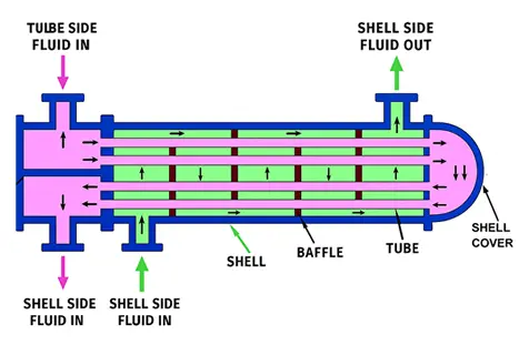
A Shell and tube heat exchanger is an industrial device designed to transfer heat efficiently between two fluids. One fluid flows through the tubes (tube side), and the other flows around the tubes inside a cylindrical shell (shell side). Heat is transferred through the tube walls. This design is ideal for high-pressure and high-temperature applications, such as:
  • Condensing steam in power plants
  • Cooling crude oil in refineries
  • Heating or cooling process fluids in chemical industries

Key Components of Shell and Tube Heat Exchangers

  1. Shell: The outer casing that houses the tube bundle.
  2. Tube Bundle: A collection of parallel tubes that facilitate heat exchange between the fluids.
  3. Tube Sheets: Sturdy sheets that secure the tubes in place and separate the shell-side fluid from the tube-side fluid. The design typically includes a fixed tube sheet at one end and a floating tube sheet at the other.
  4. Baffles: Plates that direct fluid flow around the tube bundle, enhancing heat transfer efficiency by increasing turbulence.
  5. End Caps/Heads: Connect the inlet and outlet for both fluids, ensuring proper flow through the system.

Applications Across Industries

Shell and tube heat exchangers are indispensable in various sectors:
  • Chemical Industries: Used for cooling or heating process fluids to maintain reaction conditions.
  • Oil Coolers: Essential in oil refineries to regulate fluid temperatures efficiently.
  • Air Cooled Heat Exchanger Systems: Widely used in industries where water cooling is not feasible.
  • Power Plants: Critical for waste heat recovery and steam condensation processes.
Their adaptability ensures consistent performance across diverse operating conditions.
Shell and tube heat exchanger work

How Do Shell and Tube Heat Exchangers Work?

Shell and tube heat exchangers are designed to facilitate efficient heat transfer between two fluids. Here's a breakdown of their components, how they work, and their importance in various industrial applications.
Component Description Function and Unique Insights
Shell A cylindrical container that houses the tube bundle. The shell is designed to house the shell-side fluid and is often made with corrosion-resistant materials, ensuring long-term durability even under extreme conditions.
Tube Bundle A collection of tubes arranged inside the shell. Maximizes heat transfer area, enabling efficient thermal exchange. Removable tube bundles also simplify maintenance and replacement, ensuring cost-effective upkeep.
Tube Sheets Plates that hold the tubes in place at both ends. Prevent fluid mixing between the shell and tube sides, ensuring safety and integrity. Advanced welding techniques create leak-proof seals for high-pressure applications.
Baffles Metal plates inside the shell that direct fluid flow. Enhance turbulence, improving heat transfer efficiency. They also reduce fouling by ensuring fluid flow is directed over the tubes, avoiding stagnant zones that hinder performance.
Inlet and Outlet Nozzles Openings for fluid entry and exit. These nozzles control flow rates precisely, ensuring better thermal efficiency and regulated outlet temperature in processes like cooling or heating.
Headers (Front & Rear) Chambers that distribute or collect tube-side fluid. Facilitate uniform fluid distribution across the tube bundle and provide access points for inspection or cleaning, enhancing maintenance efficiency.


Step by step explaination

1. Fluid Flow Separation

One fluid (e.g., cooling water) flows through the tubes (tube side) while another fluid (e.g., hot oil) flows around them (shell side) within the shell.
Key Insight: The two fluids stay separated by the tube walls, stopping mixing and ensuring efficient heat transfer.

2. Heat Transfer Process

Heat is transferred through conduction from one fluid to another via the tube walls.
  • In a power plant, steam on the shell side heats cooling water inside the tubes, causing the steam to turn into liquid.
  • Efficiency Tip: The thickness of the tube wall plays a crucial role in the heat transfer rate. Thin-walled tubes made of high thermal conductivity materials, like copper, are used for better efficiency.

3. Turbulence Creation via Baffles

Baffles are metal plates inside the shell. They make the shell-side fluid flow across the tubes, creating turbulence.
  • Result: This improves thermal contact, boosting heat transfer efficiency and reducing fouling buildup that can reduce performance.

4. Multiple Passes for Efficiency

Depending on design requirements, fluids may flow through single-pass or multi-pass configurations.
  • Multi-pass systems optimize heat transfer by increasing the contact time between fluids, allowing for more efficient heat exchange.

5. Phase Change Applications

In some heat exchangers, phase changes happen, like steam turning into liquid or liquid turning into gas. This is common in industries like power generation and chemical processing.
  • Example: In a thermal power plant, steam condenses to water inside the tubes, recovering heat for use in the system.

Advantages of Shell and Tube Heat Exchangers

  1. High Efficiency: These exchangers are designed to maximize heat transfer due to their large surface area and effective temperature difference between fluids.
  2. Versatility: They work well in a lot of different situations because they can handle a lot of different temperatures and pressures.
  3. Durability: Constructed from robust materials like carbon steel or stainless steel, they withstand harsh operating conditions.
  4. Ease of Maintenance: The removable tube bundle allows for easy access during cleaning and inspections.

Applications of Shell and Tube Heat Exchangers

Shell and tube heat exchangers are widely used across multiple industries:

  • Chemical Processing: Used for heating or cooling chemical reactions.
  • Power Generation: Essential for cooling steam in power plants.
  • HVAC Systems: Regulating indoor temperatures efficiently.
  • Marine Applications: Cooling systems in ships and boats.

Types of Flow Configurations

Flow Configuration Description Applications
Counterflow Fluids flow in opposite directions, maximizing temperature difference along the exchanger length. Ideal for high-efficiency systems, like power plants or refrigeration units, that need precise cooling or heating.
Parallel Flow Fluids flow in the same direction with a smaller temperature gradient compared to counterflow designs. Suitable for moderate heat transfer applications like HVAC systems or basic industrial cooling processes.
Crossflow Fluids flow perpendicular to each other, often used with baffles to enhance turbulence and efficiency. Common in air-cooled systems or compact designs where space efficiency is critical.

Design Considerations

When selecting a shell and tube heat exchanger, consider these factors:

  1. Material Selection: Choose materials based on compatibility with fluids being used; options include carbon steel or stainless steel.
  2. Size and Capacity: Determine appropriate sizes based on flow rates, including factors like shell diameter and tube length.
  3. Pressure Ratings: Ensure selected models can handle specific pressure conditions, especially if you're looking for high-pressure heat exchangers.

Technical Specifications of Shell and Tube Heat Exchangers

1. Fixed Tube Sheet Design

The Fixed Tube Sheet design is ideal for applications where the heat exchanger needs to maintain high-pressure conditions with non-corrosive fluids. The tube bundle is welded to the tube sheet, which is fixed at both ends, making it a more rigid solution for many industrial applications.
  • Pressure Rating: 10 bar to 150 bar
  • Material Options: Carbon Steel, Stainless Steel, Titanium, Copper Alloys
  • Heat Transfer Capacity: 100 kW to 1000 kW
  • Max Operating Temperature: 300°C
  • Applications: Ideal for industries like chemical processing and oil & gas, where fluids are usually not highly corrosive and the system works at a constant pressure.

2. U-Tube Design

The U-Tube design is ideal for applications with high thermal expansion and contraction or where maintenance is a priority. The flexible U-shaped tube bundle allows for expansion and contraction of the tubes without stressing the tube sheets. This design is also easier to clean, making it a preferred choice in industries with stringent maintenance needs.
  • Pressure Rating: 20 bar to 200 bar
  • Material Options: Stainless Steel, Nickel Alloys, Hastelloy
  • Heat Transfer Capacity: 200 kW to 2500 kW
  • Max Operating Temperature: 350°C
  • Applications: Suitable for high-thermal expansion environments such as petrochemical refineries, power generation, and steam condensation systems.

3. Floating Head Design

The Floating Head design is an advanced solution that simplifies the maintenance and cleaning process. In this configuration, one of the tube sheets is free to float, which allows for easier thermal expansion and contraction without putting stress on the shell and tube structure. This makes it a versatile option for a variety of industries that require ease of maintenance and long-term reliability.
  • Pressure Rating: 10 bar to 100 bar
  • Material Options: Stainless Steel, Titanium, Carbon Steel
  • Heat Transfer Capacity: 250 kW to 3000 kW
  • Max Operating Temperature: 450°C
  • Applications: Ideal for industries like chemical processing, pharmaceuticals, and food & beverage, where regular cleaning and maintenance are necessary.

4. Finned Tube Heat Exchanger Design

Finned tube heat exchangers feature tubes with attached fins to increase the heat transfer area, which makes them perfect for systems requiring high heat dissipation in a compact design. This design is especially effective when space is limited but maximum heat transfer is needed.
  • Pressure Rating: 5 bar to 50 bar
  • Material Options: Aluminum, Copper, Stainless Steel
  • Heat Transfer Capacity: 50 kW to 500 kW
  • Max Operating Temperature: 250°C
  • Applications: Common in HVAC systems, refrigeration, and power plants, where space-saving and enhanced heat transfer are critical.

5. Tube Bundle Heat Exchanger Design

The Tube Bundle heat exchanger has easily replaceable tubes, making it perfect for applications that need frequent maintenance. Its modular design allows for quick and easy tube replacement, reducing downtime during maintenance.
  • Pressure Rating: 10 bar to 150 bar
  • Material Options: Carbon Steel, Stainless Steel, Alloy Steel
  • Heat Transfer Capacity: 100 kW to 1000 kW
  • Max Operating Temperature: 350°C
  • Applications: Best suited for high-volume oil & gas and power generation applications where consistent and efficient performance is essential.

Understanding Tube Design

Tube Pitch

The spacing between tubes is referred to as the tube pitch, which affects both flow dynamics and maintenance access. Proper design ensures optimal flow patterns while minimizing fouling.

Tube Passes

The number of times the fluid passes through the tubes is known as tube passes. More passes can enhance heat transfer but may require more space.

U-Tube Exchangers

In some designs, such as U-tube exchangers, tubes are bent into a U-shape to allow for thermal expansion without stress on components.

Comparison with Other Heat Exchanger Types

Shell and Tube vs. Plate Heat Exchanger

Shell and tube exchangers are more robust for high-pressure applications compared to plate heat exchangers, which are more compact but less durable under extreme conditions.

Shell and Tube vs. U-Tube Heat Exchanger

U-tube designs allow for easier thermal expansion management but may have limitations in certain applications compared to standard shell and tube designs.

Troubleshooting Common Issues

  1. Fouling: Regular cleaning is essential to prevent buildup that reduces efficiency due to temperature differences.
  2. Leakage: Inspect for leaks regularly; prompt repairs are necessary to avoid operational issues.
  3. Performance Monitoring: Keep an eye on temperature differences between inlet and outlet fluids to ensure optimal performance.

Conclusion

Shell and tube heat exchangers are vital components in many industrial processes due to their efficiency, durability, and versatility. Their ability to facilitate effective thermal management makes them an excellent choice for businesses seeking reliable solutions for heating and cooling processes.

At United Cooling Systems, we offer high-quality shell and tube heat exchangers designed to meet your specific operational needs. Whether you require a compact solution or a robust design for demanding applications, our expertise ensures you receive a product that enhances your operational efficiency.

Ready to get started? for a free consultation and let our team of experts help you find the perfect heat exchanger for your system.

FAQ

1.What is the shell and tube in a heat exchanger?

A shell and tube heat exchanger is a type of heat exchanger that consists of a cylindrical shell containing a bundle of tubes. One fluid flows through the tubes (tube side), while another fluid flows around these tubes within the shell (shell side). This design allows for efficient heat transfer between the two fluids without them mixing, making it ideal for various industrial applications, including oil refining and chemical processing.

2.What are TEMA standards?

The Tubular Exchanger Manufacturers Association (TEMA) standards are guidelines that establish uniformity in the design, construction, and performance of shell-and-tube heat exchangers. These standards ensure quality and safety across the industry by defining specifications for materials, dimensions, and operational practices.

3.What is the working principle of a heat exchanger?

The working principle of a heat exchanger involves two fluids at different temperatures flowing close to each other. Heat is transferred from the hotter fluid to the cooler one through the walls of the tubes, allowing for efficient heating or cooling without mixing the fluids. The design can vary, with common configurations including counterflow, parallel flow, and crossflow.

4.What are the fundamentals of shell and tube heat exchangers?

The fundamentals include:
  • Heat Transfer Mechanism: Primarily through conduction across tube walls.
  • Fluid Flow Arrangement: Can be designed for various flow patterns (counterflow, parallel flow).
  • Efficiency Factors: Influenced by surface area, temperature differences, flow rates, and baffle design to enhance turbulence and heat transfer.

5.What are TEMA and ASME?

TEMA refers to the Tubular Exchanger Manufacturers Association, which focuses on standards specific to shell-and-tube heat exchangers. ASME, or the American Society of Mechanical Engineers, provides broader engineering standards applicable to various mechanical systems, including pressure vessels and heat exchangers. Both organizations play crucial roles in ensuring safety and efficiency in engineering practices.

6.What is the latest TEMA standard?

The latest TEMA standard updates reflect advancements in technology and industry practices. These updates include revisions on nomenclature, fabrication tolerances, and guidelines tailored to modern manufacturing techniques. The specifics can vary based on periodic reviews by TEMA.

7.What are the three types of TEMA specifications?

The three primary types of TEMA specifications are:
  1. TEMA R: Designed for heavy-duty applications.
  2. TEMA B: Suitable for moderate-duty applications.
  3. TEMA C: Intended for lightweight applications.

8.What is a TEMA?

A TEMA is an acronym for the Tubular Exchanger Manufacturers Association. It is an organization that develops standards for shell-and-tube heat exchangers to promote consistency in design and manufacturing across the industry.

9.What are the design standards?

Design standards for heat exchangers encompass guidelines that dictate material selection, construction methods, performance metrics, safety protocols, and maintenance practices. These standards ensure that heat exchangers operate efficiently under specified conditions while adhering to safety regulations.

10.What is the standard used for heat exchangers?

The primary standards used for heat exchangers include those set by TEMA for shell-and-tube designs and ASME for broader mechanical systems. These standards ensure quality control and safety in manufacturing processes across various applications in industries such as chemical processing and oil refining.

11.Which type of heat exchanger is mostly used?

Shell-and-tube heat exchangers are the most common because of their durability and versatility. They transfer heat efficiently between fluids, making them perfect for gas processing, steam condensation, and liquid cooling in industries like oil refining and power generation.

12.What is the best material for a shell and tube heat exchanger?

Stainless steel is widely preferred for its corrosion resistance and durability. For enhanced performance, 316L stainless steel is often used for the tube side, while 304L stainless steel is used for the shell. Other materials like titanium or Hastelloy are chosen for highly corrosive environments.

13.What is the tube length for a shell and tube heat exchanger?

Tube lengths typically range from 8 ft (2.4 m) to 40 ft (12 m), depending on design requirements. The standard length is often 20 ft (6.1 m), but longer tubes may be used in large-scale operations to optimize heat transfer efficiency.

14.What are the problems with shell and tube heat exchangers?

Fouling, caused by scale, sediment, or biological growth, is a common issue that reduces heat transfer efficiency and increases pressure drop. Regular cleaning and proper fluid velocity can help mitigate fouling risks.

15.What is the principle of shell and tube heat exchangers?

Shell-and-tube heat exchangers work by transferring heat between two fluids—one flows inside the tubes while the other flows around them in the shell. This design ensures efficient thermal exchange without mixing the fluids.

16.What is the methodology of a shell and tube heat exchanger?

The exchanger consists of a cylindrical shell housing a bundle of tubes. One fluid flows through the tubes, while another flows over them within the shell, allowing heat to transfer across the tube walls.

17.How to dismantle a shell and tube heat exchanger?

To dismantle, remove the shell cover first. Then detach brackets or supports securing the tube bundle. Carefully lift out the bundle using lifting equipment like a crane to avoid damage during maintenance or cleaning.

18.What is the pressure drop on a shell and tube heat exchanger?

The pressure drop on the shell side of a shell and tube heat exchanger typically ranges from 0.5 to 5.0 psi (0.03 to 0.35 bar). It depends on factors like baffle spacing, fluid velocity, shell diameter, and the arrangement of tubes.

19.How do you find a leak in a shell and tube heat exchanger?

To detect leaks, conduct a pressure test by pressurizing the exchanger with air, water, or another fluid. Monitor for pressure drops or use dye or ultrasonic testing to identify leak locations.
Top